Hardware setup
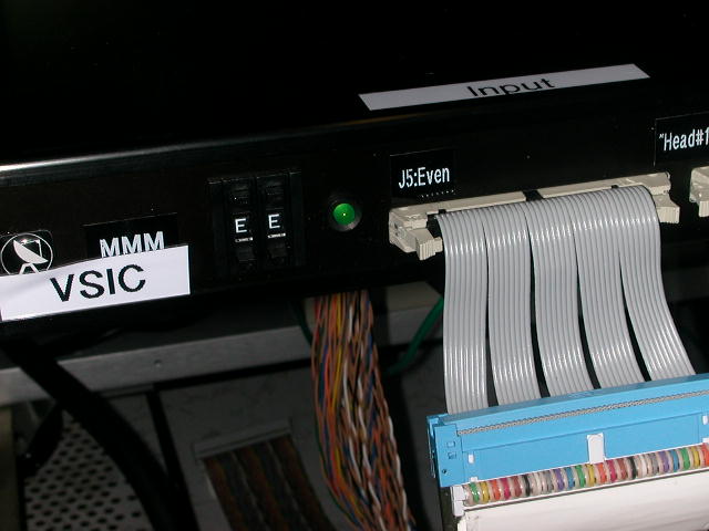
To set the VSIC card to S2 input mode, it must be set to mode E.
This is done either using the
toggle switch
or setting the 4 rocker
switches to 1110 (binary E). The VSIC also has a useful test mode where
it produces a sequence of monotonically decreasing integers. This is
useful for thorough testing of the capture software. To use the test
mode
set the VSIC to mode 6/0110.
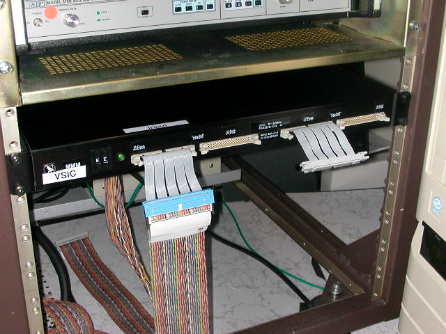
The disk recorders can be used in a number of ways. Either directly
connected to the LBA DAS, recording in parallel with the S2 and there
are a number of special modes for recording higher data rates
Direct disk recording
The
VSIC should be connected to the
S2 output port on the DAS using a
normal 50-way twist and flat cable. In this mode up to 256 Mbps data
rates can be recorded (4x16 MHz) depending on the DAS mode.
Parallel S2 recording
For realtime fringe testing, and some special experiments, it is
desirable to record data in parallel with the S2. The S2 C2a port
allows
this to be done, but the pin layout is different than for the S2 input
(ie the data and clock signals are on different pins). To record this
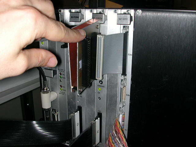
data, the BG2 cable (actually a small mounted PCB) is needed. Plug the
BG2 into the S2 C2a output port then plug a
normal 50way twist
and flat from the BG2 to the VSIC. Note that the C2a output on the S2
only makes available the signals that the S2 is recording, so that in
this mode only 128 Mbps rates can be recorded. The VSIB recording
hardware cannot record data rates less than 256 Mbps, so that half of
the received data is rubbish. The vsib_record "compression" mode (-c)
allow
this data to be discarded before recording to disk.
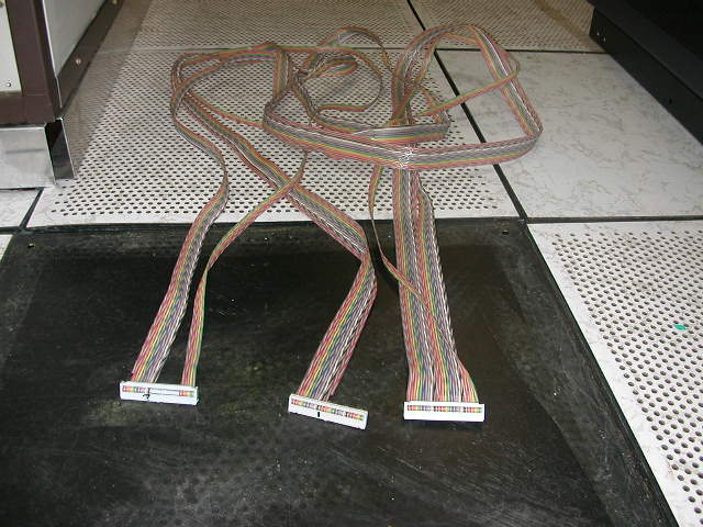
Dual DAS recording (Huygens mode)
Two DAS can be recorded in parallel using the
"Huygens"
cable. This is
a 3 headed cable where t
wo connectors
plug into the S2 output of two
DAS and the other end of the cable plugs into the VSIC. In this mode
512 Mbps data rates can be recorded (8×16 MHz). This means
vsib_record needs to be run in
mode "2"
(16 bits per sample).
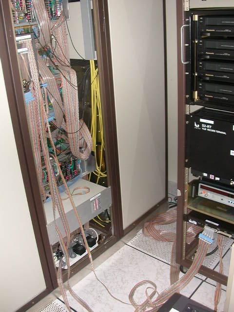
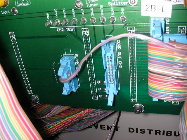
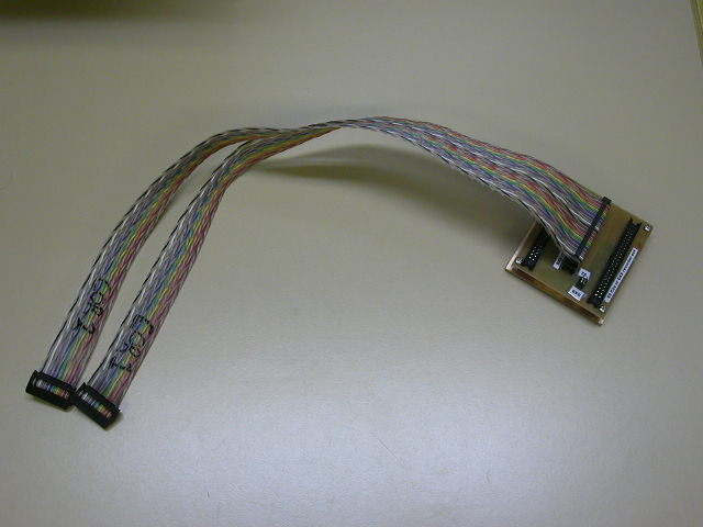
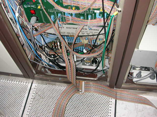
64 MHz bandwidth
The
correlator output ports on the DAS can
be configured to output 2
bit 64 MHz data directly (with no digital filtering). This allows data
rates of 512 Mbps from a single DAS (twice that from the S2 output
port). As the signal format from the correlator ports are different
from the S2 port a patch cable is needed to produce a pin assignment in
the S2 specs. The
BG3 cable does this. This PCB
has 3 inputs and one
output. Two of the inputs are 20 way twist and flat cables which
connect into the two correlator output
ports on the back of the DAS
(this supplies the sampled 64 MHz data from the two IFPs and the 32 MHz
reference clock from the first correlator output). The third input
plugs into the S2 output of the DAS to supply the 1 PPS tick. The 50
way twist-and-flat output from the BG3 then plugs into the VSIC. For
this recording mode, vsib_record needs to be run in
mode "2" (16 bits
per sample).
Please not that currently the BG3 cable does not work reliably. These
problems are being investigated.